Key Parameters
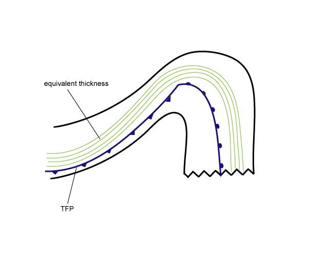
- Equivalent thickness:
The higher gradient zone of the equivalent thickness typical for a frontal zone can be found at the leading part of the cloud shield. - Thermal front parameter (TFP):
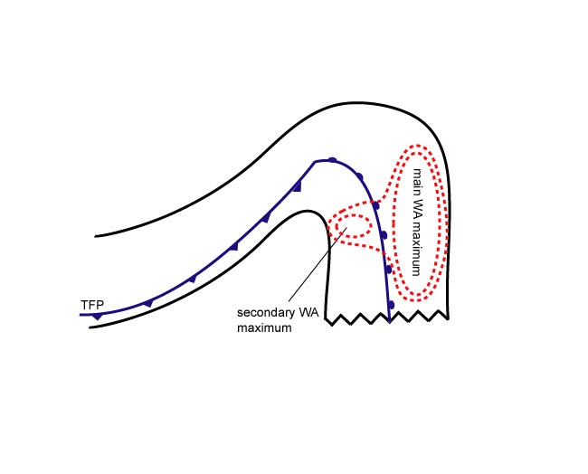
The TFP has its maximum close to the area of the surface front, which is situated within the cloud shield at the warm side of the higher gradient zone of the equivalent thickness. Consequently, no indication for the location of the surface Warm Front from the cloud image alone is possible. - Warm advection (WA):
The whole cloudiness of the Warm Front Shield (frontal cloudiness as well as the cloudiness of the warm sector) is within more or less strongly pronounced WA. Like the Warm Front described before (see Warm Front Band - Key parameters ), the field of WA increases towards the Occlusion point. Therefore its maximum can be found, in the case of an eastward moving frontal system, in the northern part of the cloud shield. A second, usually less pronounced, WA maximum can be found within the central part of the cloud shield (the warm sector). While the first maximum represents the Warm Conveyor Belt ascending to the surface frontal zone, the second maximum represents the Warm Conveyor Belt ascending to the upper level frontal zone (see Typical appearance in vertical cross section). - Shear vorticity at 300 hPa:
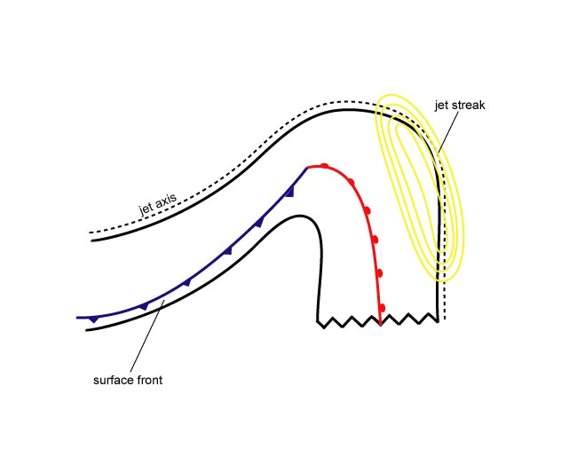
The zero line coincides with the leading edge of the Warm Front cloud shield. - Isotachs at 300 hPa:
The leading edge of the Warm Front cloud shield is superimposed upon a jet streak.
|
03 January 2005/12.00 UTC - Meteosat 8 IR 10.8 image; blue: thermal front parameter 500/850 hPa, green:
equivalent thickness 500/850 hPa
|
|
|
|
|
03 January 2005/12.00 UTC - Meteosat 8 IR 10.8 image; blue: thermal front parameter 500/850 hPa, red: temperature
advection 500/1000 hPa
|
|
|
|
|
03 January 2005/12.00 UTC - Meteosat 8 IR 10.8 image; yellow: isotachs 300 hPa, black: zero line of shear vorticity 300 hPa
|
|
|
|