Table of Contents
Cloud Structure In Satellite Images
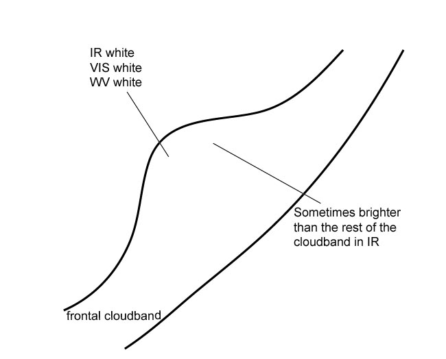
The satellite image shows a cloud bulge at the rear edge of the cloud band of a cold front;
Appearance in the basic channels:
- In the VIS and IR images the area of the cloud bulge is white, indicating thick and/or multi-level cloud;
- In the IR image the grey shades can be brighter than the rest of the cloud band;
- In the initial stage, the rearward cloud edge takes the form of an S-shape, which becomes more pronounced over time;
- At a later stage a cloud spiral develops from the cloud bulge:
- In some cases the spiral develops directly from the white cloud bulge (see Occlusion: Warm Conveyor Belt Type );
- In some cases the spiral develops as a low cloud, emerging beneath the higher cloud layers; in this case it seems that the two synoptic layers are decoupled (see Occlusion: Cold Conveyor Belt Type ).
Appearance in the basic RGBs:
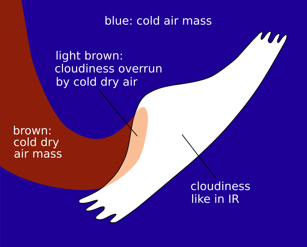
Airmass RGB
The protrusion of cold and dry air at the rearward side of a wave is indicative of the initial stages of cyclogenesis. Therefore, dark blue colours exist at the rear side. Depending on the stages of development, a brown stripe immediately behind the S-shape of the wave also exists.
The wave bulge cloud looks very similar to the IR image. Sometimes a brown-ish shadow above the wave bulge indicates overrunning dry air.
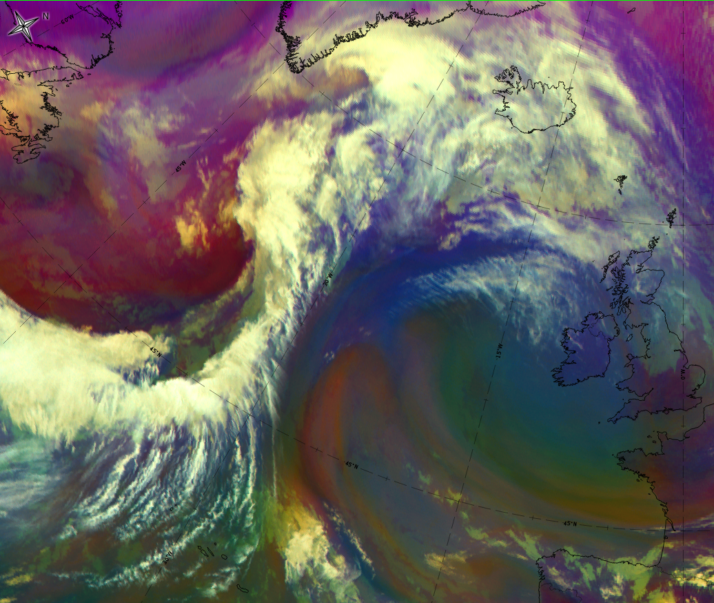
Dust RGB
Despite from other existing cloud configurations, the dust RGB shows blue to pinkish blue colours, representing cloud-free regions. There is often low-level cloud which shows up in ochre colours.
The wave cloud bulge consists of the dark red areas which are representing thick as well as the convective cloud regions. Very often it is more colour-intensive compared with the eastern part of the cold front band.
 |
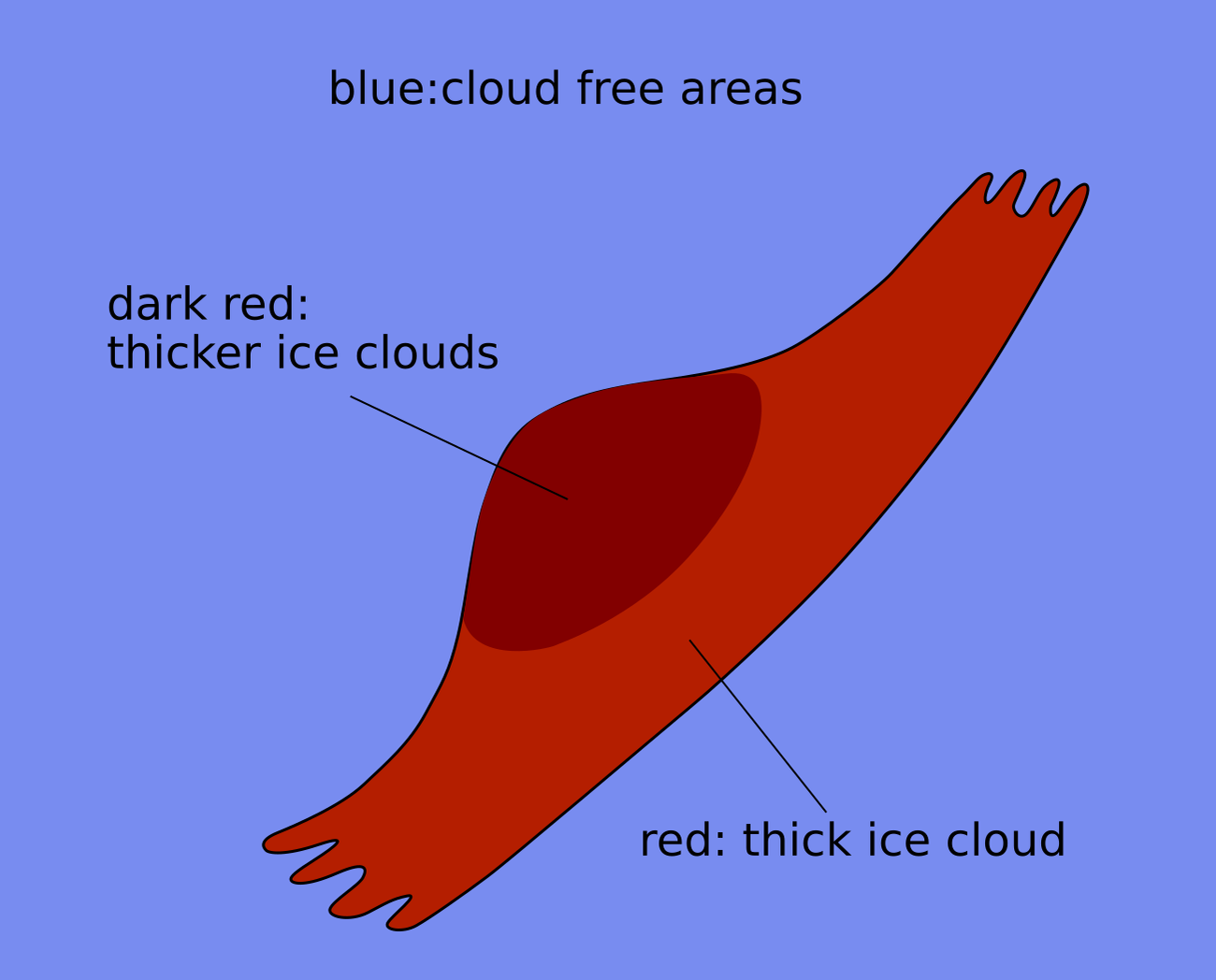 |
Legend: schematics for basic RGBs. Left: airmass RGB; right: dust RGB.
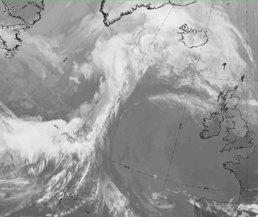
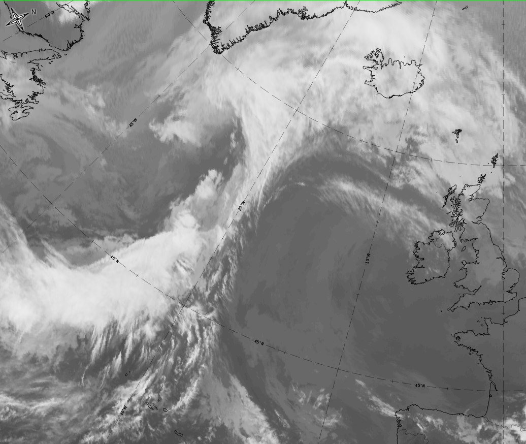
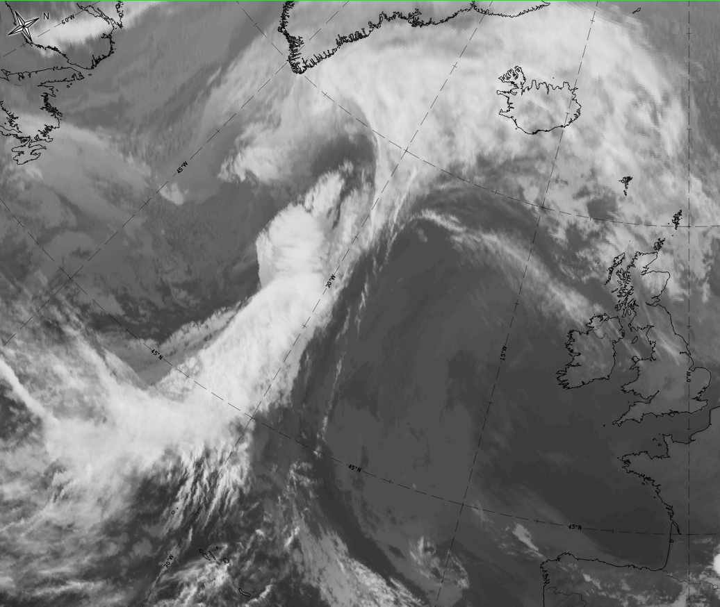
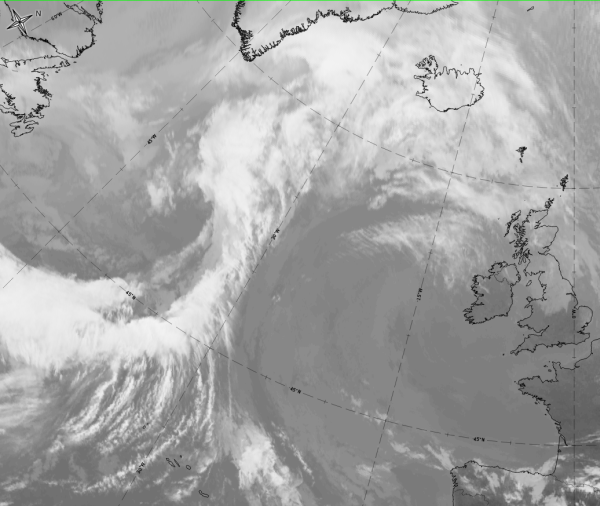
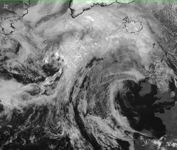
The case of 18 September 2019 at 12 UTC shows both: the development of a wave bulge into an occlusion cloud spiral, and the typical cloud appearance in the basic channels and basic RGBs.

|
|
|
|
Legend:
18 September 2019 from 12 to 21 UTC: Development from wave to occlusion stage
*Note: click on the image to access the image gallery (navigate using arrows on keyboard)
|
|
|
|
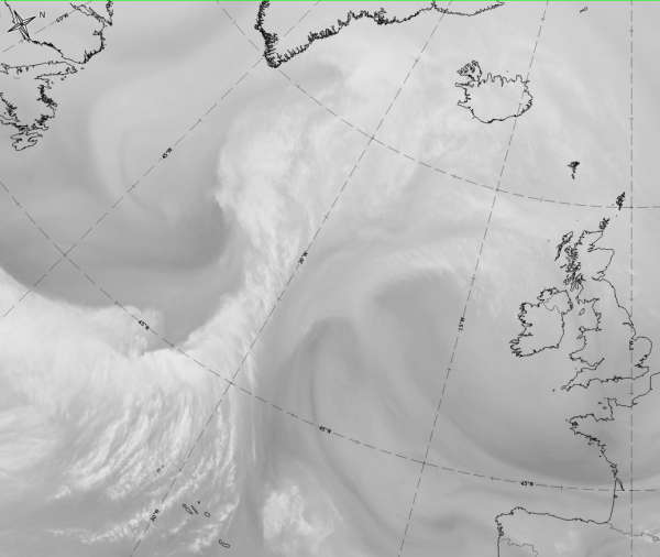

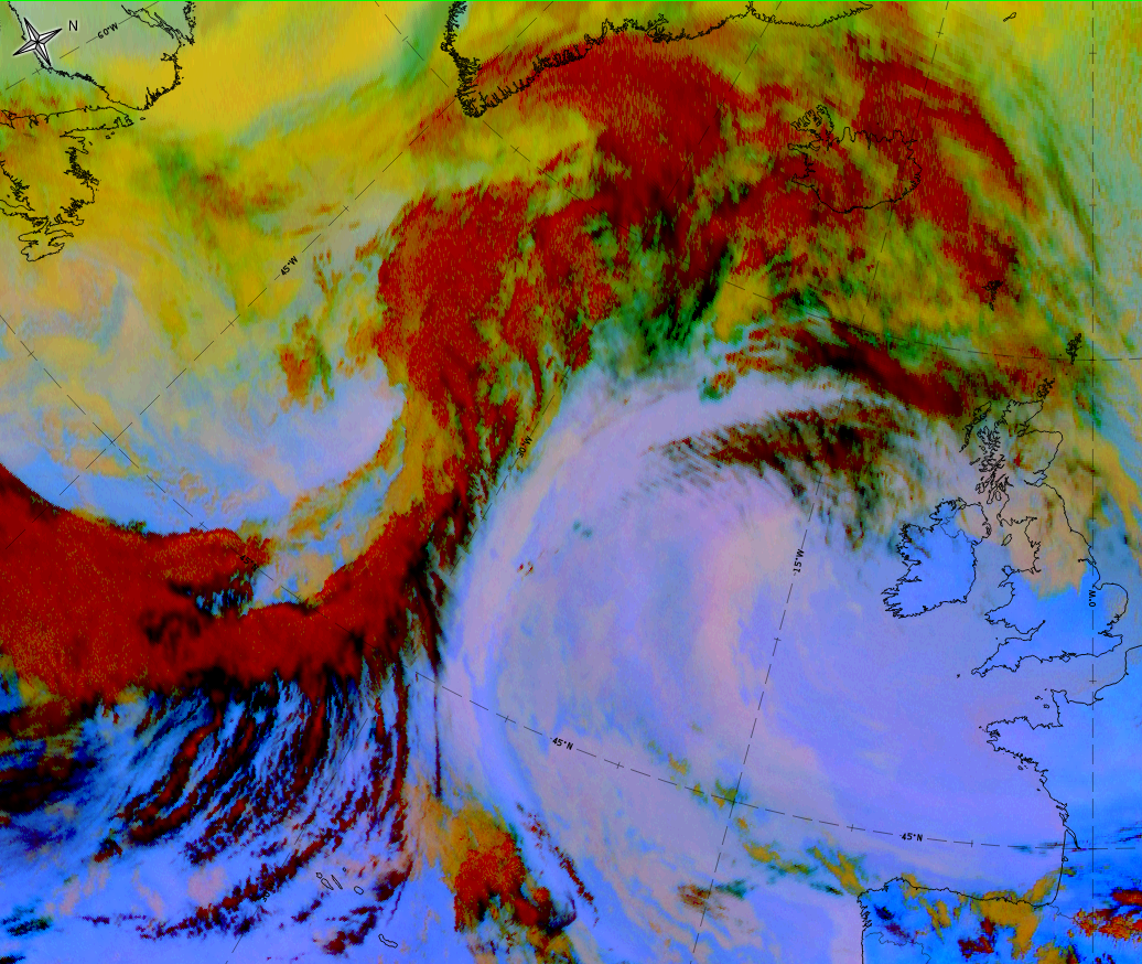
Legend: 18 September 2019 at 12UTC: 1st row: IR (above) + HRV (below); 2nd row: WV (above) + Airmass RGB (below); 3rd row: Dust RGB + image gallery.
*Note: click on the Dust RGB image to access image gallery (navigate using arrows on keyboard)
| IR | White and lumpy texture indicates cold cloud tops with convective characteristics. |
| HRV | White and lumpy texture indicates cold cloud tops with convective characteristics. |
| WV | White and lumpy texture; the dark stripe at the rear represents sinking dry air. |
| Airmass RGB | Clouds are similar to their appearance in IR; the dark brown area at the rear corresponds to the dark stripe in WV, indicating the dry sinking air at the rear of the wave. |
| Dust RGB | A dark red colour and a lumpy texture indicates thick ice cloud with convective characteristics. |
Meteorological Physical Background
A Wave development can be treated as a substructure in a Cold Front and indicates the initial stage of cyclogenesis. There are several conceptual models describing Wave development:
- Wave development in a frontogenetic pattern
- Behaviour of stable and unstable Waves
- Cyclogenesis due to superposition of upper level vorticity maxima
- Downstream and upstream development of baroclinic waves
- Orographic cyclogenesis
According to well-known polar front theory a low pressure area in the lower levels of the troposphere can develop if a small-scale disturbance is superimposed on the synoptic-scale air stream (see Key parameters ). This small-scale disturbance is caused by a transverse circulation within the baroclinic zone of the Cold Front. The transverse circulation is released by frontogenesis in the horizontal wind field that causes a fall in pressure, convergence and the production of cyclonic vorticity in the lower levels of the troposphere at the warm edge of the baroclinic zone. The consequence of this disturbance is that cold air moves south-eastward and warm air moves north-westward; this circulation is superimposed on the eastward-moving front. During this circulation a strengthening of the low pressure area occurs (as long as the frontogenesis continues) and further development of a new cyclone can be observed.
Looking only at the kinematic processes a very simple description of the development of the S-shape cloudiness as well as the typical distribution of the temperature advection field can be given. The cyclonic vorticity deforms the cloud band edge and transports cold and warm air, leading to typical positions of WA and CA maxima(see Key parameters ). The WA maximum as well as PVA within the cloud bulge, indicating the deepening of the low, contributes to the increase of cloudiness in the Wave area.
|
|
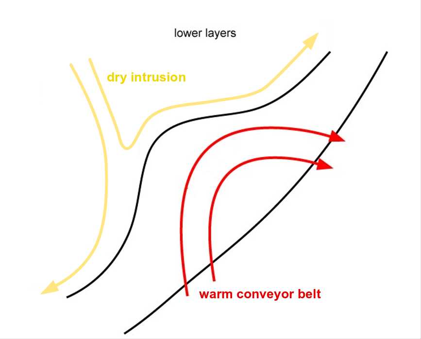
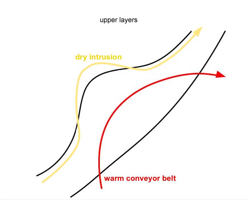
Conveyor belt theory has proved to be a valuable tool for providing additional insight into the development and behaviour of fronts. There are only very few investigations concerning Wave areas and the following summary is only based on about four cases. Therefore only the main common features are mentioned. While in the case of a frontal cloud band without a Wave relative streams are more or less oriented parallel to the cloud band (see Cold Front ), in the case of the cloud bulge of a Wave a small scaled substructure within the stream lines can be observed:
- a strongly ascending Warm Conveyor Belt accompanies the area of the cloud bulge;
- the dry intrusion approaches the warm conveyor belt, forming a limiting stream line between both streams very close to the cloud edge;
- the higher the isentropic level the more this stream overruns the cloud bulge - this part is less bright in the WV image and is sometimes accompanied by cloud fibres in the IR image which are at the rear of the cloud bulge - this effect appears only in a very small region and is not yet well understood;
- in the lower isentropic layers relative stream lines immediately south of the Wave form a saddle point - this is a consequence of the cyclonic circulation in the Wave area in the lower layers.
|
|
Wave development as described in this chapter is one type accompanying the initial stages of cyclogenesis. Some other types and their conceptual models can be found in this manual within the chapters:
- Rapid Cyclogenesis (see Rapid Cyclogenesis )
- Instant Occlusion (see Instant Occlusion )
|
16 April 2005/00.00 UTC - Vertical cross section; black: isentropes (ThetaE), orange thin: IR pixel values, orange thick: WV pixel values
|
16 April 2005/00.00 UTC - Meteosat IR image; magenta: relative streams 304K - system velocity: 181° 13 m/s1, yellow: isobars 304K, position of vertical cross section indicated
|
|
|
As can be seen in the vertical cross section the isentropic surface of 304K is a relatively low surface. Relative streams show a Warm Conveyor Belt within the Wave bulge, which in this case seems to be shifted a bit too far to the north. It rises from about 800 hPa up to 500 hPa and the limiting stream line between this stream and the one from behind the cloud band coincides relatively well with the cloud edge.
Key Parameters
- Warm advection (WA):
The field of temperature advection is characterized by a juxtaposition of a WA maximum within the cloud bulge and a CA maximum in the dry air behind. This indicates the circulation of air masses within the deepening low (see Meteorological physical background ). In reality the WA maximum can be rather weak while usually a pronounced CA maximum exists behind the cloud bulge. The zero line of the temperature advection passes through the bulge and should mark the centre of the Wave. - Positive vorticity advection (PVA):
A PVA maximum is superimposed upon the cloud bulge in the higher levels of the troposphere (500 and 300 hPa), indicating the deepening of a low. Both (WA and PVA) are responsible for the production of the increased cloudiness of the Wave bulge. - Absolute topography at 1000 and 500 hPa:
In the absolute topography at lower levels of the troposphere (for instance at 1000 hPa) a low pressure area can be observed which often manifests itself as a pronounced trough but sometimes already shows a weak closed circulation, intensifying during the life cycle. In upper levels, for instance at 500 hPa, a large scale trough can usually be observed with cloudiness in the south-western stream. - Isentropic potential vorticity (IPV):
According to Hoskins (1986) anomalies of IPV representing very dry stratospheric air can be regarded as being connected with cyclogenesis. The approach of an IPV anomaly at higher levels in the direction of a low level baroclinic zone may cause cyclogenesis. From present knowledge the Waves described in this chapter are not a typical example for such a development, but very often an anomaly develops upstream on the rear side of the Wave at higher levels around approximately 300 hPa; this is accompanied by the development of a black area in the WV image.
|
04 July 2005/12.00 UTC - Meteosat 8 IR 10.8 image; green: PVA max at 500 hPa; magenta: height contours at 1000 hPa; red: temperature advection 700 hPa
|
|
|
|
|
04 July 2005/12.00 UTC - Meteosat 8 IR 10.8 image; red: temperature advection 500/1000 hPa, green: positive vorticity advection 500 hPa
|
|
|
|
|
04 July 2005/12.00 UTC - Meteosat 8 IR 10.8 image; cyan: height contours 500 hPa, green: positive vorticity advection 500 hPa
|
|
|
|
|
04 July 2005/12.00 UTC - Meteosat 8 WV 6.2 image; magenta: height of isentropic potential vorticity = 1
|
|
|
|
Typical Appearance In Vertical Cross Sections
The convection associated with a Wave is well reflected in the vertical cross sections shown below. From the Wave point a vertical cross section was drawn though the frontal band. Weather symbols which are plotted on the images reflect its convective character and give indications of rain, snow and thunderstorms, respectively. For the various parameters the following can be concluded:
- Isentropes :
Isentropes show mainly frontal character. No impact from Wave. - Temperature Advection:
Maximum at 300 hPa or at higher levels, associated with tropopause folding (related to potential vorticity), cold advection below the Wave bulge at lower levels. - Vorticity Advection:
Significant maximum of positive vorticity advection at upper levels connected to the sharpening of the upper level trough at 300 hPa. - Vertical motion:
Vertical motion indicates rising air, with the maximum at upper levels, due to a rising upper relative stream.
|
04 July 2005/12.00 UTC - Meteosat 8 IR 10.8 image; position of vertical cross section indicated
|
|
|
|
Temperature advection: vertical cross sections from numerical model
|
04 July 2005/12.00 UTC - Vertical cross section; black: isentropes (ThetaE), red thin: temperature advection - CA, red thick: temperature advection - WA, orange thin: IR pixel values, orange thick: WV pixel values
|
|
|
|
Positive vorticity advection: vertical cross sections from numerical model
|
04 July 2005/12.00 UTC - Vertical cross section; black: isentropes (ThetaE), green thin: vorticity advection - NVA, green thick: vorticity advection - PVA, orange thin: IR pixel values, orange thick: WV pixel values
|
|
|
|
Vertical motion (Omega): vertical cross sections from numerical model
|
04 July 2005/12.00 UTC - Vertical cross section; black: isentropes (ThetaE), cyan: vertical motion (omega) - upward motion, orange thin: IR pixel values, orange thick: WV pixel values
|
|
|
|
Potential vorticity: vertical cross sections from numerical model
|
4 July 2005/12.00 UTC - Vertical cross section; black: isentropes (ThetaE), dark green thin: potential vorticity <1 unit, dark green thick: potential vorticity >=1 unit, orange thin: IR pixel values, orange thick: WV pixel values
|
|
|
|
Weather Events
| Parameter | Description |
| Precipitation |
|
| Temperature |
|
| Wind (incl. gusts) |
|
| Other relevant information |
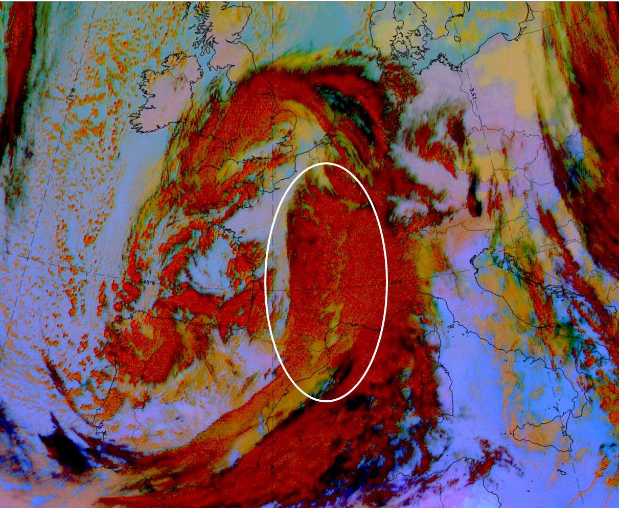
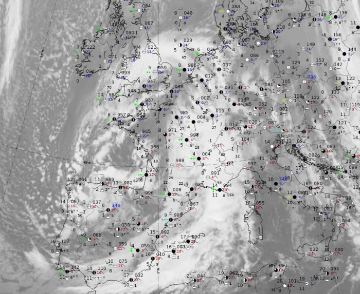
As example for studying the weather events in the area of a wave the case of 14 November 2019 at 12 UTC has been chosen. The S-shape is very pronounced but there is double structure. Together with other parameters, this double structure means that the centre of the wave development is located within the centre of the white ellipse in the figure below.
|
|
Legend:
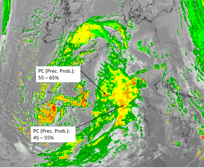
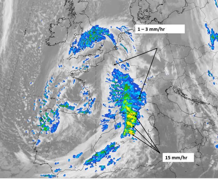
14 November 2019 at 12UTC: IR + synoptic measurements (above) + probability of moderate rain (Precipitting clouds PC - NWCSAF).
Note: for a larger SYNOP image click this link.
There are widespread and heavy precipitation rate measurements in the area and in the centre of the cloud bulge. To the western and northern boundary, only overcast observations exist; this appears quite often and represents the outflowing high cloudiness in the direction of the upper level stream.
|
|
|
|
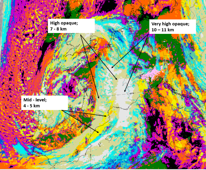
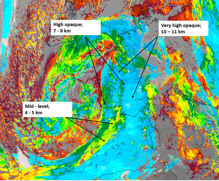
14 November 2019 at 12 UTC;
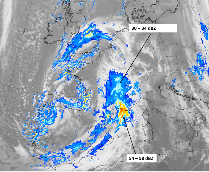
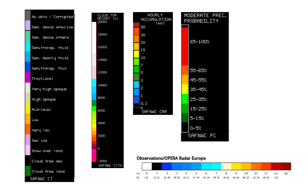
1st row: Cloud Type (CT NWCSAF) (above) + Cloud Top Height (CTTH - NWCSAF) (below); 2nd row: Convective Rainfall Rate (CRR NWCSAF) (above) + Radar intensities from Opera radar system (below).
For identifying values for Cloud type (CT), Cloud type height (CTTH), precipitating clouds (PC), and Opera radar for any pixel in the images look into the legends. (link).
Wave - Special Investigation: Waves with Double Structure
Appearance in satellite images
In addition to the Waves described in this CM which show an increasing cloud bulge at the rear of frontal cloud bands, there is a sub-group of Waves which show a double structure of Wave configurations with the brighter cloud tops in the leading (usually more eastern) Wave feature and lower cloud tops and even dissipation in the rearward (usually more western) Wave feature; at the end of the process cloud upstream from the main cloud bulge has largely disappeared. In WV images there is a clear indication that upper level processes are involved. In this manual, this subtype is called "Double Structure Wave". Such situations occur quite often; the presentation below is based on an investigation of four cases of "Double Structure Waves".
It should be noted that a third type of Wave ("Upper Wave") is described in this manual (see Upper Wave ). Whether all three are different types of Waves or wether they are connected still has to be determined.
The two diagrams below show a simplified development of classical and Double Structure Waves.
|
|
In the case of a classical Wave (left) a cloud bulge increases in size and curvature. During the development a Dark Stripe seen in the WV image intensifies along and parallel to the rear side of the frontal cloud band. Quite often, convective clouds develop at the leading edge of the Dark Stripe which is also a position close to the maximum cloud bulge.
In the case of a "Double Structure Wave" two approximately parallel Wave bulges develop early in the development. During the development a Dark Stripe (in WV) overruns the rear part of the double structure leading to a further lowering of cloud tops in that region. Consequently, there must be quite an abrupt dissipation of the rearward Wave cloud.
The 6-hourly loops below left show IR and WV images of a classical Wave, those on the right a "Double Structure Wave". The classical Wave images also show the development of Cb clouds over mid Italy moving into the northern Adriatic Sea. This cloud phenomenon should not be confused with the increasing Wave bulge which moves from Austria southeastwards to Slovenia and Croatia.
 Loop: 27 April 2002 06.00 - 15.00 UTC 3-hourly image loop Loop: 27 April 2002 06.00 - 15.00 UTC 3-hourly image loop
|
Loop: 16 November 2000 00.00 - 15.00 UTC 3-hourly image loop
|
|
27 April 2002/06.00 UTC - Meteosat IR image; Classical Wave
|
16 November 2000/00.00 UTC - Meteosat IR image; Double Structure Wave
|
|
|
|
|
|
27 April 2002/06.00 UTC - Meteosat WV image; Classical Wave
|
16 November 2000/06.00 UTC - Meteosat WV image; Double Structure Wave
|
|
Loop: 27 April 2002 06.00 - 15.00 UTC 3-hourly image loop
|
Loop: 16 November 2000 06.00 - 15.00 UTC 3-hourly image loop
|
Meteorological Physical Background
WV imagery strongly shows the involvement of the upper relative stream and the dry intrusion in the "Double Structure Wave". The following diagrams, derived from several cases, show the typical distribution of conveyor belts and the difference between the two Wave types.
|
In the classical Wave a Warm Conveyor Belt is the main cause of cloudiness within the cloud bulge. In the "Double Structure Wave" the Warm Conveyor Belt can only be found well in front of the Wave bulge, at the leading edge of the front. It is the upper relative stream which can be more clearly identified in the area of the Wave bulge. Also the dry intrusion overruns the rear part of the Wave, resulting in cloud dissipation.
The two images below demonstrate these findings. There is an extended Warm Conveyor Belt in the main part of the Wave bulge whilst in the second case the Warm Conveyor Belt is far in front of the "Double Structure Wave". There is an upper relative stream and a dry intrusion overrunning the more westerly Wave cloud.
|
27 April 2002/12.00 UTC - Meteosat IR image; yellow: isobars, magenta: relative streams 308K - system velocity: 262° 10 m/s
|
16 November 2000/06.00 UTC - Meteosat IR image; yellow: isobars, magenta: relative streams 314K - system velocity: 244° 15 m/s
|
|
|
Key Parameters
Surface Low
As the diagram below shows, the surface low is close to the point of inflection of the "S" - shaped rearward cloud boundary of the classical Wave (left). This is also true for the "Double Structure Wave" (right) but the low is associated with the leading Wave configuration.
Upper level trough and PVA max
In the case of a classical Wave (left) the upper level trough lies some distance from the cloud feature resulting in the PVA max lying mainly at the rear of the Wave bulge. In the case of a "Double Structure Wave" the upper level trough line is very close to the rearward Wave resulting in the PVA max being situated more above the cloud of this Wave.
|
The images below support this configuration. In the classical Wave (left) there is an intensive surface trough immediately south of the Wave bulge; in the "Double Structure Wave" there is a closed surface low close to the leading Wave formation and a secondary trough in the surface height near to the rearward (more westerly) cloud bulge.
|
27 April 2002/06.00 UTC - Meteosat IR image; magenta: height contours 1000 hPa
|
16 November 2000/06.00 UTC - Meteosat IR image; magenta: height contours 1000 hPa
|
|
|
Upper level trough and PVA max are shown in the two images below. The PVA max lies behind the frontal cloud and the Wave bulge in the case of a classical Wave but is superimposed on the lower cloud of the rearward Wave in the "Double Structure Wave".
|
27 April 2002/06.00 UTC - Meteosat IR image; cyan: height contours 500 hPa; green: positive vorticity advection 500 hPa
|
16 November 2000/06.00 UTC - Meteosat IR image; cyan: height contours 500 hPa; green: positive vorticity advection 500 hPa
|
|
|
Height of PV (PV anomalies)
When looking at the field of potential vorticity (height of PV = 2 units), differences can be seen between the two types of Wave: In case of the classical Wave (left) the gradient of height of PV = 2 units is immediately behind the frontal cloud within the area of the WV Dark Stripe, in the case of the "Double Structure Wave" it lies above the rearward Wave. In both cases, the area of lowest height of stratospheric PV is behind the whole cloud system but much further away in case of the classical Wave. All cases investigated showed a good correspondence between the rearward edge of the cloud (leading system for the "Double Structure Wave") and the 300 hPa isolines.
|
The two examples below show these differences very well. Particularly clear in the "Double Structure Wave" is the coincidence between the high gradient of height of PV = 2 units and the dark grey cloud band to the rear.
|
27 April 2002/06.00 UTC - Meteosat IR image; magenta: height of PV = 2 units
|
16 November 2000/06.00 UTC - Meteosat IR image; magenta: height of PV = 2 units
|
|
|
Conclusion
For the double structure wave there seems to be a distinct influence of the upper level trough and its accompanied PVA. The rearward Wave feature seems to be the result of PVA and vorticity (preferably curvature vorticity; see Upper Wave). However, at the same time sinking dry air with high values of PV is overrunning this second cloud feature, leading to the typical lowering and dissipation of cloud (compare Rapid Cyclogenesis). Another upper level influence, running hand in hand with these processes, is a possible interaction between stratospheric PV (PV anomaly) and the surface low, which consequently can be associated with the leading Wave feature.
References
General Meteorology and Basics
- BROWNING K. A. (1985): Conceptual models of precipitation systems; Quart. J. R. Meteor. Soc., Vol. 114, p. 293 - 319
- BROWNING K. A. (1986): Conceptual models of precipitation systems; Weather&Forecasting, Vol. 1, p. 23 - 41
- CONWAY B. J., GERARD L., LABROUSSE J., LILJAS E., SENESI S., SUNDE J. AND ZWATZ-MEISE V. (1996): COST78 Meteorology - Nowcasting, a survey of current knowledge, techniques and practice - Phase 1 report, Office for official publications of the European Communities
- HOSKINS B. J., MCINTYRE M. E. and ROBERTSON A. L. W. (1985): On the use and significance of isentropic potential vorticity maps; Quart. J. R. Meteor. Soc., Vol. 111, p. 877 - 946
- KURZ M. (1990): Synoptische Meteorologie - Leitfäden für die Ausbildung im Deutschen Wetterdienst; 2. Auflage, Selbstverlag des Deutschen Wetterdienstes
- LILJEQUIST G. H. and CEHAK K. (1984): Allgemeine Meteorologie, 3. Auflage, Braunschweig, Vieweg
- ZWATZ-MEISE V. and MAHRINGER G. (1990): SATMOD: An interactive system combining satellite images and model output parameters; Weather&Forecasting, Vol. 5, p. 233 - 246
General Satellite Meteorology
- BADER M. J., FORBES G. S., GRANT J. R., LILLEY R. B. E. and WATERS A. J. (1995): Images in weather forecasting - A practical guide for interpreting satellite and radar imagery; Cambridge University Press
- ZWATZ-MEISE V. (1987): Satellitenmeteorologie; Springer Verlag, Berlin - Heidelberg - New York - London - Paris - Tokyo
Specific Satellite Meteorology
- BROWNING K. A. and GOLDING B. W. (1994): Mesoscale effects of a dry intrusion within a vigorous cyclone; JCMM - internal report 29
- MARTIN J. E., LOCATELLI J. D. and HOBBS P. V. (1992): The synoptic evolution of a deep tropospheric frontal circulation and attendant cyclogenesis; 5th Conference on Mesoscale Processes, Atlanta, Georgia, 5 - 10 January 1992