The steps of creating a new RGB scheme
RGB images are created by visualizing three spectral channels or channel combinations (e.g. difference, ratio) in the three primary colors.
The process of building a new RGB scheme has five steps.
Step 1: Determine the purpose of the product.
Step 2: Based on experience or scientific information, select three appropriate channels or channel combinations that provide useful information for the specific purpose.
Step 3: Proper enhancement: pre-process the single channels (or channel combinations) to ensure that they provide or emphasize the most useful information.
Step 4: Assign the three spectral channels or channel combinations to the three RGB color components.
Step 5: Test the resulting RGB for appearance and effectiveness.
Let us discuss the above steps one-by-one.
Step 1: Determine the purpose
The following questions should be considered.
- Do we intend to create an RGB for general cloud analysis, or for focusing on a special phenomenon?
- Should it be applicable day and night?
- In which time period (season) and geographical region is it supposed to work best?
Step 2: Based on experience or scientific information, select three appropriate channel combinations (which can simply be a single channel) that provide useful information for the specific purpose.
Which channel combinations are sensitive to the features we want to highlight?
- The selection should be based on the physical properties represented by the channels. Table 1 may help.
- Put three different features into the color beams. It does not make sense to combine channel combinations that represent exactly the same physical property!
Table 1 lists several FCI channels and channel combinations with their information content.
| VIS0.4, VIS0.5 | Cloud optical thickness, aerosols |
| VIS0.6 | Cloud optical thickness |
| VIS0.8 | Cloud optical thickness, "greenness" of vegetation |
| VIS0.9 | Low-level moisture, total precipitable water |
| NIR1.3 | Thin cirrus clouds, high-level aerosols |
| NIR1.6, NIR2.2, IR3.8 (reflective part) | Cloud top microphysics (particle size and phase), fire |
| WV6.3, WV7.3 | Mid- and upper-level moisture |
| IR8.7, IR10.5, IR12.3, IR3.8 (thermal radiation part) | Cloud top temperature |
| IR8.7 - IR10.5 | Cloud phase and optical thickness, volcanic SO2 gas |
| IR12.3 - IR10.5 | Cloud optical thickness, moisture, dust, volcanic ash |
| IR3.8 - IR10.5 during night | Cloud phase |
| IR13.3 - IR10.5 | Cloud top height |
| WV6.3 - IR10.5 | Cloud top height |
| IR9.7 - IR10.5 | Stratospheric O3 amount (indirectly: airmass type) |
| WV6.2 - WV7.3 | volcanic SO2 gas |
| VIS0.9/VIS0.8 or (VIS0.9-VIS0.8)/(VIS0.9+VIS0.8) or logVIS0.8-logVIS0.9 |
Low-level moisture, total precipitable water |
Table 1: Information content of several FCI channels and channel combinations
Remarks:
- The channel names in Table 1 consist of characters and numbers. VIS stands for visible, NIR for near-infrared, IR for infrared and WV for infrared water vapor absorbing band; the number indicates the central wavelength in µm.
- Channel combinations are often channel difference (between the calibrated values), as with the IR channels here. They can also be a ratio or a logarithmic difference, as with VIS0.9 here.
Step 3: Carry out a proper enhancement of the chosen channel combinations (including single channels) to highlight features of interest.
The chosen channel combinations are pre-processed (one-by-one) to highlight the information with a high brightness contrast.
Substeps:
- Conversion from radiances to brightness temperatures or reflectivity values.
- Selection of display mode (inverted or not inverted);
- Choosing the brightness temperature or reflectivity ranges we would like to highlight.
- Stretching these ranges linearly (stretching of the active dynamic range);
- Performing non-linear stretching (e.g. gamma correction), if needed.
Remarks:
- For the visible channels (below ~0.6 µm central wavelength) it is recommended to perform Raleigh correction (to eliminate the effect of molecular scattering) as with the True Color RGB.
- For solar channels usually it is recommended to perform a solar zenith angle correction for the calibrated values.
- The purpose of the pre-processing is that all color beams should have good contrast, especially for the phenomena the given RGB component focuses on.
- Definition of the visualization mode:
- Non-inverse visualization: pixels with smaller values appear in darker shades, while pixels with larger values appear in brighter shades.
- Inverse visualization: pixels with smaller values appear in brighter shades, while pixels with higher values appear in darker shades (this is how single infrared images are visualized for weather forecasters).
- During the pre-processing we often choose a narrower range of the calibrated values than the whole intensity range. The “range of interest” depends on which phenomena we would like to highlight (high clouds, low clouds, surface features, dust …).
- The range of interest can be chosen by using radiative transfer model calculations, or experimentally.
- The image shades are stretched within this range. First linearly, then a non-linear stretching might be also applied.
- For calibrated values within the range of interest, the output (representing the brightness) is set between 0 and 255.
- For calibrated values lower than the minimum of the range, the brightness is set to zero, while for calibrated values higher than the maximum of the range the brightness is set to 255 (in the case of non-inverse visualization).
- The developer might choose non-linear stretching in order to focus on an interval of lower/higher values within the range of interest. In many RGBs, gamma correction is used as non-linear stretching, but other methods can also be used, for example piecewise linear stretching. For more information on gamma correction, see the appendix.
Step 4: Color assignment of the three pre-processed spectral channels or channel combinations to the three RGB color beams
The final appearance of the RGB images strongly depends on the color assignment. All the possible color assignment combinations contain the same information since they are based on the same three input channels (or channel combinations), but they have radically different color schemes.
Some 'official' recommendations help to decide how to assign the pre-processed channels (or channel combinations) to the color beams:
- The recommended color assignment for RGBs focusing on cloud top microphysics is:
- Red: cloud optical thickness
- Green: cloud top microphysics
- Blue: temperature of radiating surface
- The resulting RGB should contain as many natural colors for clouds and surface features as possible.
- The sensitivity of the human eye is not equal in the primary colors, see Fig. 1. It is therefore useful to assign the component reflecting the most important phenomenon in the green color beam, and the least important in the blue color beam.
- The assignment may also depend on the personal preference of the creator.
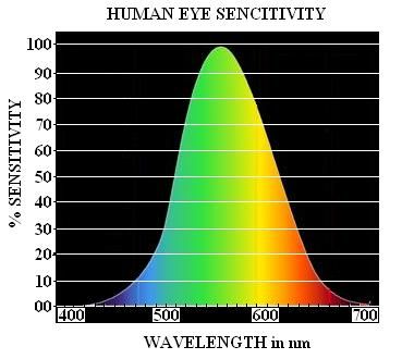
Fig. 1: Sensitivity of human eye
Step 5: Testing the newly created RGB composite and reviewing for appearance and effectiveness
When creating a new RGB scheme, several tests are performed to find the optimal channels (channel combinations), proper enhancement and color assignment. The tests are first performed for a few cases and then for more and more cases. After the preliminary tuning, the RGB must be tested for very many cases covering different illumination conditions, seasons, geographical areas and weather situations to review its appearance and effectiveness.
If the RGB turns out to be useful and is to be recommended for use by others, the outcome of the testing should be included: for which purpose and in which circumstances does it work well, which other RGBs does it complement, etc.
After Steps 1-5, the final RGB scheme can be described by a recipe. The recipe of an RGB contains all the information needed to create it: which channel (or channel combination) is visualized in which color beam, and how they are enhanced (ranges, gamma parameters); see more information in the appendix and in the chapter "Example".